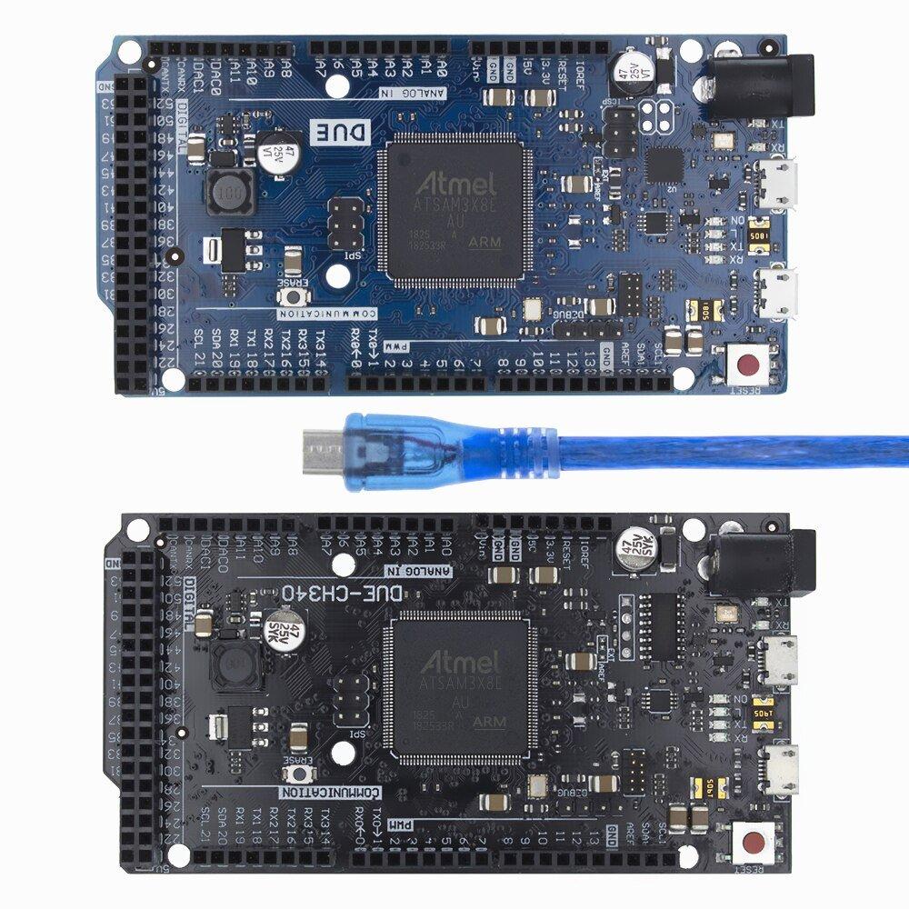
In this article we look at another Arduino board, the Arduino Due
We will assume you are migrating from an Arduino Uno or Mega (same size or form factor), so lets point out some important considerations and differences.
The Due has 12 Analog inputs versus 16 on the Arduino Mega 2560
The Due is only 3.3v tolerant, not 5v – very important this one as this can damage your board if you supply too much voltage especially to that analog ins.
The Due has 12 PWM pins versus 15 on the Mega
You may experience difficulty with existing Uno shields – the SPI is only on the ICSP header, the I2C pins are not on A4 or A5 and the 3.3v maximum voltage. Due to these factors the shield may not function
I have also seen libraries that have Due specific code, usually conditional statements to make things work but there is no guarantee that these will all work without modification.
There are 2 USB ports on this one – a native one and a programming one. You can use both to program the board and both are available as options in the IDE but it is recommended that you use the Programming port which actually uses a ATmega16U2 to communicate with the AT91SAM3X8E rather than a direct connection to a port on the SAM3X
You can use the Due to emulate a USB mouse or keyboard to an attached computer. This is similar to the leonardo.
Features
The SAM3X has 512 KB (2 blocks of 256 KB) of flash memory for storing code
| Microcontroller | AT91SAM3X8E |
| Operating Voltage | 3.3V |
| Input Voltage (recommended) | 7-12V |
| Input Voltage (limits) | 6-16V |
| Digital I/O Pins | 54 (of which 12 provide PWM output) |
| Analog Input Pins | 12 |
| Analog Output Pins | 2 (DAC) |
| Total DC Output Current on all I/O lines | 130 mA |
| DC Current for 3.3V Pin | 800 mA |
| DC Current for 5V Pin | 800 mA |
| Flash Memory | 512 KB all available for the user applications |
| SRAM | 96 KB (two banks: 64KB and 32KB) |
| Clock Speed | 84 MHz |
Power
The power pins are as follows:
- Vin. The input voltage to the board when it’s using an external power source. You can supply voltage through this pin, or, if supplying voltage via the power jack, access it through this pin.
- 5V. This pin outputs a regulated 5V from the regulator on the board. The board can be supplied with power either from the DC power jack (7 – 12V), the USB connector (5V), or the VIN pin of the board (7-12V). Supplying voltage via the 5V or 3.3V pins bypasses the on-board regulator, and can damage the board.
- 3V3. A 3.3 volt supply generated by the on-board regulator. Maximum current draw is 800 mA.
- GND. Ground pins.
- IOREF. This pin on the board provides the voltage reference with which the microcontroller operates. A properly configured shield can read the IOREF pin voltage and select the appropriate power source or enable voltage translators on the outputs for working with the 5V or 3.3V.
Pins
Each of the 54 digital pins on the Due can be used as an input or output. They are not 5v tolerant and operate at 3.3v. 3 mA or 15 mA is the maximum currecnt available depending on the pin
The Mega 2560 has 16 analog inputs, each of which provide 12 bits of resolution. By default, the resolution of the readings is set at 10 bits, for compatibility with other Arduino boards. It is possible to change the resolution of the ADC with analogReadResolution(). The Due’s analog inputs pins measure from ground to a maximum value of 3.3V.
Serial: Serial: 0 (RX) and 1 (TX), Serial 1: 19 (RX) and 18 (TX), Serial 2: 17 (RX) and 16 (TX), Serial 3: 15 (RX) and 14 (TX. These are only 3.3v though.
External Interrupts: 2 (interrupt 0), 3 (interrupt 1), 18 (interrupt 5), 19 (interrupt 4), 20 (interrupt 3), and 21 (interrupt 2). These pins can be configured to trigger an interrupt on a low level, a rising or falling edge, or a change in level.
PWM: Available on Pins 2 to 13. Provide 8-bit PWM output.
SPI: The SPI pins are broken out on the central 6-pin header, which is physically compatible with the Uno, Leonardo and Mega2560.
LED: 13. There is a built-in LED connected to digital pin 13. When the pin is HIGH the LED is on, when the pin is LOW, it’s off. It is also possible to dim the LED because the digital pin 13 is also a PWM output.
TWI/I2C : 20 (SDA) and 21 (SCL) and TWI 2: SDA1 and SCL1.
CAN: CANRX and CANTX but not supported in the IDE
DAC1 and DAC2 : These pins provides true analog outputs with 12-bits resolution (4096 levels) with the analogWrite() function. These pins can be used to create an audio output using the Audio library. The DAC output range is actually 0.55 V to 2.75 V only.
AREF. Reference voltage for the analog inputs. Used with analogReference().
Reset. Bring this line LOW to reset the microcontroller. Typically used to add a reset button to shields which block the one on the board.
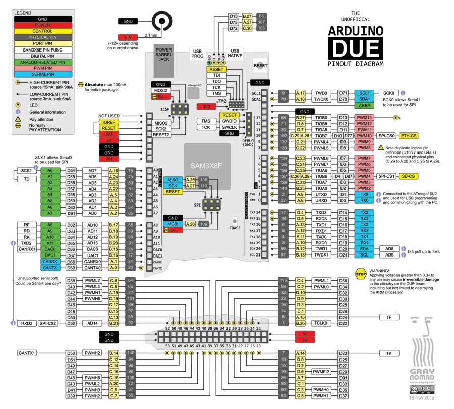
Here is a pinout of the board
Installation
The board works out the box with the desktop IDE and the online IDE.
Many examples online
Cost
| Site | Link | Price |
| Amazon.com | OSOYOO Due R3 32 Bit ARM Compatible Shield Module Board with USB Cable | $33.99 |
| Aliexpress | Due R3 Board Main Control Board with USB Cable for arduino | $24.50 |
| Amazon.co.uk | Arduino Due [A000062] | £38.65 |
Summary
If you need more I/O pins and more code space then this board is ideal.
Compatibilty may be an issue if you are coming from an Arduino Uno or a Mega