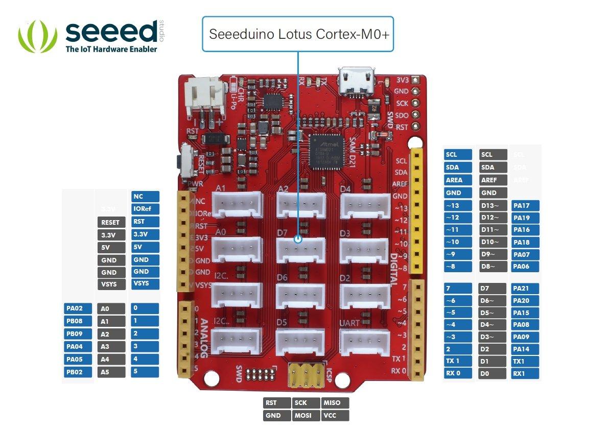
In this article we look at the Seeeduino Lotus Cortex-M0+.
If you have an Arduino shield you should realise that the SPI connections are only available on the ICSP connector, so if it does not connect to the Seeeduino Lotus Cortex-M0+ 6-pin ICSP header, the shield will not work.
Also it does not A4 or A5 for I2C – so if the shield was connected to those pins then it will not work with this board.
The pins are 3.3v tolerant only – something else to be wary of if you are coming from an Arduino
The Seeeduino Lotus Cortex-M0+ female header is fully compatible with Arduino UNO
If you have grove sensors or modules there are 12 on-board Grove connectors
Features
| Item | Value |
|---|---|
| Microcontroller | SAM D21 |
| Power Input | Micro-USB JST2.0 |
| Operating Voltage | USB:5V Lipo:3.5V~4.2V |
| Digital I/O Pins | 14 |
| PWM Channels | 10 |
| Analog Input Channels | 6 |
| DC Current per I/O Pin | 40 mA |
| IO Input Voltage | 3.3V |
| SRAM | 32 KB |
| Flash Memory | 256KB |
| Maximum CPU frequency | 48 MHz |
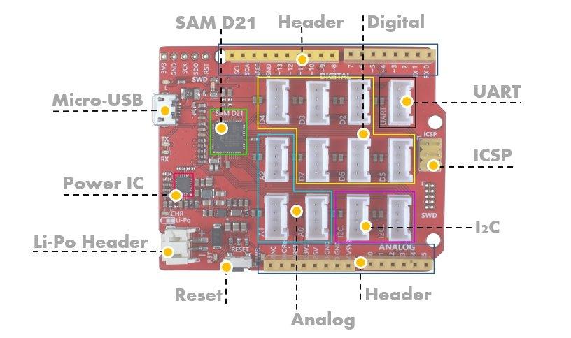
Power
You can use both USB and Li-Po battery supply for Seeeduino Lotus Cortex-M0+. Also, you can use this board to charge your Li-Po battery.
When you power the board with USB and plug the Li-Po battery at the same time, the Li-Po battery will be charged, and the CHR LED will flash. After the battery is fully charged, the CHR LED will stop flashing.
Pins
Each of the 14 digital pins on the Seeed Lotus can be used as an input or output. They are all 5 volt tolerant. A maximum of 40mA is the value that must not be exceeded to avoid damaging the microcontroller.
The Seeeduino Lotus Cortex-M0+ has 6 analog inputs, each of which provide 10 bits of resolution. By default they measure from ground to 3.3 volts.
Serial: We provide 3 hardware UART Port, one Grove UART, TX-RX pins in the header, and Multiplexed function pin SCK SDO in the SWD port. Only two hardware UART are available. Serial corresponds to Grove UART, and Serial1 corresponds to RX-TX in the header zone.
PWM: D3,D4,D5,D6,D8,D9,D10,D11,D12,D13,. Provide 8-bit PWM output
SPI: on the ICSP header. These pins support SPI communication.
LED: 13. There is a built-in LED connected to digital pin 13. When the pin is HIGH value, the LED is on, when the pin is LOW, it’s off.
Analog Inputs: A0-A5. The Seeeduino Lotus Cortex-M0+ has 6 analog inputs, labeled A0 through A5, all of which can also be used as digital i/o.
There are 12 grove digital connectors, 2 I2C, 3 analog, 6 digital and 1 UART connectors
Here is a pinout of the board showing the grove connectors
Installation
The board works with the desktop IDE but you need to support for the board
Open your Arduino IDE, click on File > Preferences, and copy below url to Additional Boards Manager URLs
https://raw.githubusercontent.com/Seeed-Studio/Seeed_Platform/master/package_legacy_seeeduino_boards_index.json
Click on Tools > Board > Board Manager.
Cost
| Site | Link | Price |
| Amazon.com | Seeeduino Lotus V1.1 – ATMega328 Board with Grove Interface | $23.30 |
| Aliexpress | Development Boards & Kits – ARM Seeeduino Lotus Cortex-M0+ | $13.86 |
| Amazon.co.uk | Seeeduino Lotus Cortex-M0+ | £18.57 |
Summary
A well designed board which is well supported, if you have grove sensors or modules then the built in connectors may be useful.