LinkIt ONE is an open-source, high-performance 8-in-1 wireless development board, based on the world’s leading wearable SOC – MediaTek Aster (MT2502A) processor. LinkIt ONE integrates a high-performance Wi-Fi (MT5931) and GPS (MT3332) x chip. The LinkIt ONE provides an interface compatible with Arduino UNO can easily intervention Shield and various sensors.
Now as we mentioned in the previous statement you can use the Arduino IDE if you want to develop for your Linkit ONE
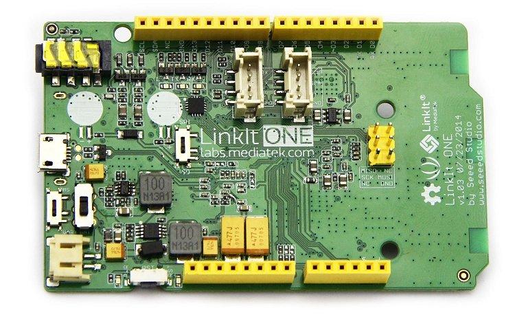
Mediakit One hardware Setup
This is from the Seedstudio website. The LinkIt one has three switches to control different functions or modes, as shown below:

1. Programming mode switch
MS mode: the program does not run, when LinkIt ONE into the computer when a pop-up about 10M removable disk, you can store the entered file or files to compile generated .vxp run onto the inside
Uart mode: the program will run correctly, it can micro USB cable can LinkIt ONE program (switch 1 down)
2. Power select switch
BAT: battery-powered, in the case where only battery power, this can be used as switches. You need to be charged when it should switch to the BAT, while inserting USB, then actually programmable.
USB: USB power supply, without battery inserted, the system will work only choose USB (switch 2 up)
3. SD / SPI selector switch
SPI: When you need to use an external SPI pins (D10 ~ D13), it should to switch to SPI
SD: If you LinkIt ONE of TF card slot TF card is inserted, and hope that through content code to access the card, you should select the SD mode, D10 ~ D13 pins at this time the board is unavailable.
So if you look at the picture switches 1 and 2 are correctly setup if you are using USB to program via the Arduino IDE
Arduino IDE Setup
- Download the latest version of the Arduino IDE , it has to be version 1.6.5 or higher, here.
- From within the Arduino IDE, go to File->Preferences dialog box.
- Look at the text box entry field called “Additional Boards Manager URLs:”.
- Paste the following URL into that text field “http://download.labs.mediatek.com/package_mtk_linkit_index.json”. Then click OK to close.
- Now select the Tools->Board->Board Manager menu from the Arduino IDE, and it will open up the Boards Manager window. From there, scroll down until you see the LinKit ONE device.
- Now choose a LinKit ONE board from the Tools->Board menu and choose the MTK USB Debug port
When I connected my board there were 3 COM ports pointing to the Linkit One, to find the MTK USB Debug Port open the Device Manager in Windows and its clearly shown under Ports(COM and LPT)
Test Program
The blink Arduino sketch will flash the on board LED
[codesyntax lang=”cpp”]
int led = 13;

// the setup routine runs once when you press reset:
void setup() {
  // initialize the digital pin as an output.
  pinMode(led, OUTPUT);
}

// the loop routine runs over and over again forever:
void loop() {
  digitalWrite(led, HIGH);   // turn the LED on (HIGH is the voltage level)
  delay(1000);               // wait for a second
  digitalWrite(led, LOW);    // turn the LED off by making the voltage LOW
  delay(1000);               // wait for a second
}
[/codesyntax]