In this article we look at a board called a Easy Module Mix V1, its another cool board with many features that makes it ideal for beginners – it’s not an Arduino shield though – it’s a standalone board that can be connected to any development board like an Arduino, ESP32, ESP8266, Micro:bit or a Raspberry Pi.
Lets look at the board
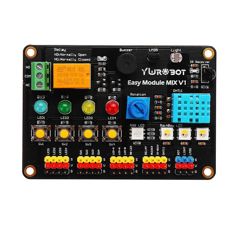
It has the following components on it
DHT11 temperature and humidity sensor
LM35 temperature sensor
IR reciever
Light dependent resistor
Buzzer
4 LEDs – 1 each of red, green, yellow, blue
1 RGB LED
1 potentiometer
1 relay
3 rainbow LEDs
4 buttons
So as you can see there are many components that you can use. You simply connect connecting wire from your development board to the particular component(s) pin that you want, you do not need to connect all the Gnd’s or Vcc’s – just one as they are all connected together.
Sample Arduino code
The LED’s are easy to run, this is not the most optimized code example but shows the LEDs on the board flashing on and off. We used D4 – D7 you could use any pin you want
[codesyntax lang=”cpp”]
int led1 = 4;
int led2 = 5;
int led3 = 6;
int led4 = 7;

// the setup routine runs once when you press reset:
void setup()
{
  // initialize the digital pin as an output.
  pinMode(led1, OUTPUT);
  pinMode(led2, OUTPUT);
  pinMode(led3, OUTPUT);
  pinMode(led4, OUTPUT);
}

// the loop routine runs over and over again forever:
void loop() {
  digitalWrite(led1, HIGH);   // turn the LED on (HIGH is the voltage level)
  delay(1000);               // wait for a second
  digitalWrite(led1, LOW);    // turn the LED off by making the voltage LOW
  delay(1000);               // wait for a second
  digitalWrite(led2, HIGH);   // turn the LED on (HIGH is the voltage level)
  delay(1000);               // wait for a second
  digitalWrite(led2, LOW);    // turn the LED off by making the voltage LOW
  delay(1000);               // wait for a second
  digitalWrite(led3, HIGH);   // turn the LED on (HIGH is the voltage level)
  delay(1000);               // wait for a second
  digitalWrite(led3, LOW);    // turn the LED off by making the voltage LOW
  delay(1000);               // wait for a second
  digitalWrite(led4, HIGH);   // turn the LED on (HIGH is the voltage level)
  delay(1000);               // wait for a second
  digitalWrite(led4, LOW);    // turn the LED off by making the voltage LOW
  delay(1000);               // wait for a second
}
[/codesyntax]
Same idea for the RGB LED, this will flash red, green and blue – you could also mix the colors by switching more on at the same time or even use PWM
[codesyntax lang=”cpp”]
int redLed = 4;
int greenLed = 5;
int blueLed = 6;


// the setup routine runs once when you press reset:
void setup()
{
  // initialize the digital pin as an output.
  pinMode(redLed, OUTPUT);
  pinMode(greenLed, OUTPUT);
  pinMode(blueLed, OUTPUT);

}

// the loop routine runs over and over again forever:
void loop() {
  digitalWrite(redLed, HIGH);   // turn the LED on (HIGH is the voltage level)
  delay(500);               // wait for a second
  digitalWrite(redLed, LOW);    // turn the LED off by making the voltage LOW
  delay(500);               // wait for a second
  digitalWrite(greenLed, HIGH);   // turn the LED on (HIGH is the voltage level)
  delay(500);               // wait for a second
  digitalWrite(greenLed, LOW);    // turn the LED off by making the voltage LOW
  delay(500);               // wait for a second
  digitalWrite(blueLed, HIGH);   // turn the LED on (HIGH is the voltage level)
  delay(500);               // wait for a second
  digitalWrite(blueLed, LOW);    // turn the LED off by making the voltage LOW
  delay(500);               // wait for a second
}
[/codesyntax]
Link
The board costs about £13 and you can get it from this link