The Wemos Mini is one of my favourite development boards for the ESP8266, one of the biggest plus points is the amount of useful little shields that can just be plugged into the wemos mini.
In this article we will look at some of these shields and show you some examples for some of my favourite shields
Parts List
This is the list of shields
| Name | Link |
| BMP180 shield | For Wemos BMP180 Digital Barometric Pressure Sensor Module |
| Ambient light shield | |
| DS18b20 shield | Shield for WeMos D1 mini V2 DS18B20 Single-bus digital temperature and humidity sensor module sensor |
| SHT30 shield | SHT30 Shield for D1 Mini |
| RGB shield | |
| OLED shield | 0.66″ inch 64X48 IIC I2C OLED LED LCD Display Shield for Arduino Compatible WeMos D1 mini |
Shields
BMP180 Shield example
An overview of a PIR
this was another shield that did not appear on the Wemos site, this time it was for the BMP180 sensor
Here is a picture of the shield
Lets talk about the BMP180.
The BMP180 is the new digital barometric pressure sensor of Bosch Sensortec, with a very high performance, which enables applications in advanced mobile devices, such as smartphones, tablet PCs and sports devices. It follows the BMP085 and brings many improvements, like the smaller size and the expansion of digital interfaces.
The ultra-low power consumption down to 3 μA makes the BMP180 the leader in power saving for your mobile devices. BMP180 is also distinguished by its very stable behavior (performance) with regard to the independency of the supply voltage.
| Parameter | Technical data |
|---|---|
| Pressure range | 300 … 1100 hPa |
| RMS noise expressed in pressure | 0.06 hPa, typ. (ultra low power mode) 0.02 hPa, typ. (ultra high resolution mode) |
| RMS noise expressed in altitude | 0.5 m, typ. (ultra low power mode) 0.17 m, typ. (ultra high resolution mode) |
| Relative accuracy pressure VDD = 3.3 V |
950 … 1050 hPa/ ±0.12 hPa @ 25 °C/ ±1.0 m 700 … 900 hPa/ ±0.12 hPa 25 … 40 °C/ ±1.0 m |
| Absolute accuracy p = 300…1100hPa (Temperature = 0…+65°C, VDD = 3.3. V) |
Pressure: -4.0 … +2.0 hPa Temperature: ±1 °C, typ. |
| Average current consumption (1 Hz data refresh rate)
Peak current |
3 μA, typical (ultra-low power mode) 32 μA, typical (advanced mode)650 μA, typical |
| Stand-by current | 1.62 … 3.6 V |
| Supply voltage VDDIO | 1.62 … 3.6 V |
| Supply voltage VDD | 1.8 … 3.6 V |
| Operation temp. Range full accuracy” |
-40 … +85 °C |
Code
This example uses the adafruit bmp085 library, you can add this via the library manager
[codesyntax lang=”cpp”]
#include <Wire.h>
#include <Adafruit_BMP085.h>

Adafruit_BMP085 bmp;

void setup()
{
  Serial.begin(9600);
  //Wire.begin (4, 5);
  if (!bmp.begin())
  {
    Serial.println("Could not find BMP180 or BMP085 sensor at 0x77");
    while (1) {}
  }
}

void loop()
{
  Serial.print("Temperature = ");
  Serial.print(bmp.readTemperature());
  Serial.println(" Celsius");

  Serial.print("Pressure = ");
  Serial.print(bmp.readPressure());
  Serial.println(" Pascal");


  Serial.println();
  delay(5000);
[/codesyntax]
Open the serial monitor and you should see something like this
Temperature = 27.30 Celsius
Pressure = 99934 Pascal
Temperature = 32.20 Celsius
Pressure = 99965 Pascal
Temperature = 32.90 Celsius
Pressure = 99968 Pascal
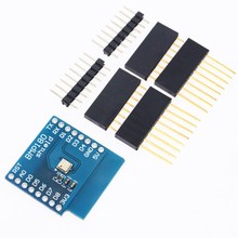
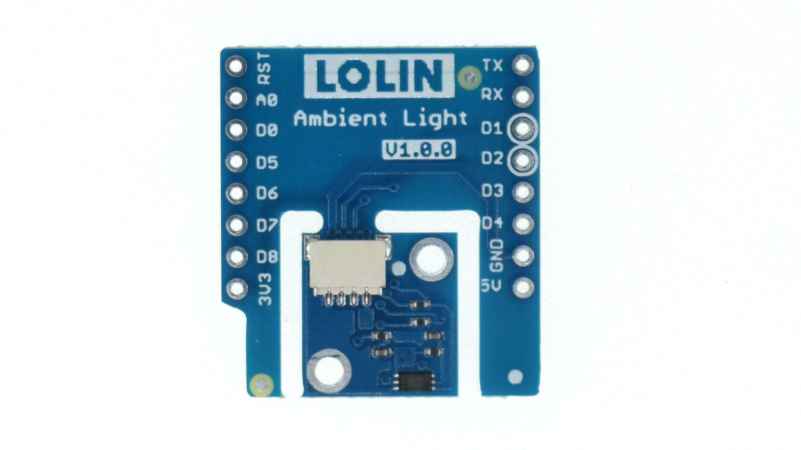
Ambient light Shield Example
This was another new shield for the Wemos called the Ambient light Shield , this time its based around the BH1750FVI digital Ambient Light Sensor
Lets look at some info about the sensor
The BH1750FVI is an digital Ambient Light Sensor IC for I2C bus interface.
This IC is the most suitable to obtain the ambient light data for adjusting LCD and Keypad backlight power of Mobile phone.
It is possible to detect wide range at High resolution. ( 1 – 65535 lx ).
Features
1) I2C bus Interface ( f / s Mode Support )
2) Spectral responsibility is approximately human eye response
3) Illuminance to Digital Converter
4) Wide range and High resolution. ( 1 – 65535 lx )
5) Low Current by power down function
6) 50Hz / 60Hz Light noise reject-function
7) 1.8V Logic input interface
8) No need for any external parts
9) It is possible to select 2 different I2C addresses
10) Adjustable measurement result for influence of optical window ( It is possible to detect min. 0.11 lx, max. 100000 lx by using this function. )
11) Small measurement variation (+/- 20%)
Being an I2C device it uses D1 and D2 on the Wemos mini
Code
You need to install the following library for this example : https://github.com/claws/BH1750
[codesyntax lang=”cpp”]
#include <Wire.h>
#include <BH1750.h>


BH1750 lightMeter(0x23);

void setup(){

  Serial.begin(9600);

  // Initialize the I2C bus
  Wire.begin();

  if (lightMeter.begin(BH1750::CONTINUOUS_HIGH_RES_MODE))
  {
    Serial.println(F("BH1750 Advanced begin"));
  }
  else
  {
    Serial.println(F("Error initialising BH1750"));
  }

}


void loop()
{
  uint16_t lux = lightMeter.readLightLevel();
  Serial.print("Light: ");
  Serial.print(lux);
  Serial.println(" lx");
  delay(1000);
}
[/codesyntax]
Open the serial monitor, cover the sensor, shine light on the sensor
Light: 29 lx
Light: 29 lx
Light: 22 lx
Light: 0 lx
Light: 0 lx
Light: 20 lx
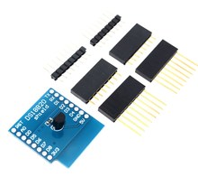
DS18b20 Shield Example
I was interested to see that searching through popular electronic component sites a DS18B20 shield for the Wemos mini, I couldn’t find a link on the Wemos site so I was intrigued and purchased one.
Here is what the shield looks like
 DS18B20 Shield for Wemos D1 mini DS18B20
Looking at the shield I could see that it used D2 as the input
Lets look at some info about the sensor
The DS18B20 digital thermometer provides 9-bit to 12-bit Celsius temperature measurements and has an alarm function with nonvolatile user-programmable upper and lower trigger points.
The DS18B20 communicates over a 1-Wire bus that by definition requires only one data line (and ground) for communication with a central micro-processor.
In addition, the DS18B20 can derive power directly from the data line (“parasite power”), eliminating the need for an external power supply.
Each DS18B20 has a unique 64-bit serial code, which allows multiple DS18B20s to function on the same 1-Wire bus. Thus, it is simple to use one microprocessor to control many DS18B20s distributed over a large area
Code
[codesyntax lang=”cpp”]
#include <OneWire.h>

// OneWire DS18S20, DS18B20, DS1822 Temperature Example

OneWire  ds(D2);  // on pin D4 (a 4.7K resistor is necessary)

void setup(void)
{
  Serial.begin(9600);
}

void loop(void)
{
  byte i;
  byte present = 0;
  byte type_s;
  byte data[12];
  byte addr[8];
  float celsius, fahrenheit;

  if ( !ds.search(addr))
  {
    ds.reset_search();
    delay(250);
    return;
  }

  if (OneWire::crc8(addr, 7) != addr[7])
  {
      Serial.println("CRC is not valid!");
      return;
  }

  // the first ROM byte indicates which chip
  switch (addr[0])
  {
    case 0x10:
      type_s = 1;
      break;
    case 0x28:
      type_s = 0;
      break;
    case 0x22:
      type_s = 0;
      break;
    default:
      Serial.println("Device is not a DS18x20 family device.");
      return;
  }

  ds.reset();
  ds.select(addr);
  ds.write(0x44, 1);        // start conversion, with parasite power on at the end
  delay(1000);
  present = ds.reset();
  ds.select(addr);
  ds.write(0xBE);         // Read Scratchpad

  for ( i = 0; i < 9; i++)
  {
    data[i] = ds.read();
  }

  // Convert the data to actual temperature
  int16_t raw = (data[1] << 8) | data[0];
  if (type_s) {
    raw = raw << 3; // 9 bit resolution default
    if (data[7] == 0x10)
    {
      raw = (raw & 0xFFF0) + 12 - data[6];
    }
  }
  else
  {
    byte cfg = (data[4] & 0x60);
    if (cfg == 0x00) raw = raw & ~7;  // 9 bit resolution, 93.75 ms
    else if (cfg == 0x20) raw = raw & ~3; // 10 bit res, 187.5 ms
    else if (cfg == 0x40) raw = raw & ~1; // 11 bit res, 375 ms

  }
  celsius = (float)raw / 16.0;
  fahrenheit = celsius * 1.8 + 32.0;
  Serial.print("  Temperature = ");
  Serial.print(celsius);
  Serial.print(" Celsius, ");
  Serial.print(fahrenheit);
  Serial.println(" Fahrenheit");
}
[/codesyntax]
Open the serial monitor
Temperature = 26.81 Celsius, 80.26 Fahrenheit
Temperature = 27.81 Celsius, 82.06 Fahrenheit
Temperature = 28.44 Celsius, 83.19 Fahrenheit
SHT30 Shield Example
This time we look at the SHT30 shield from Wemos.
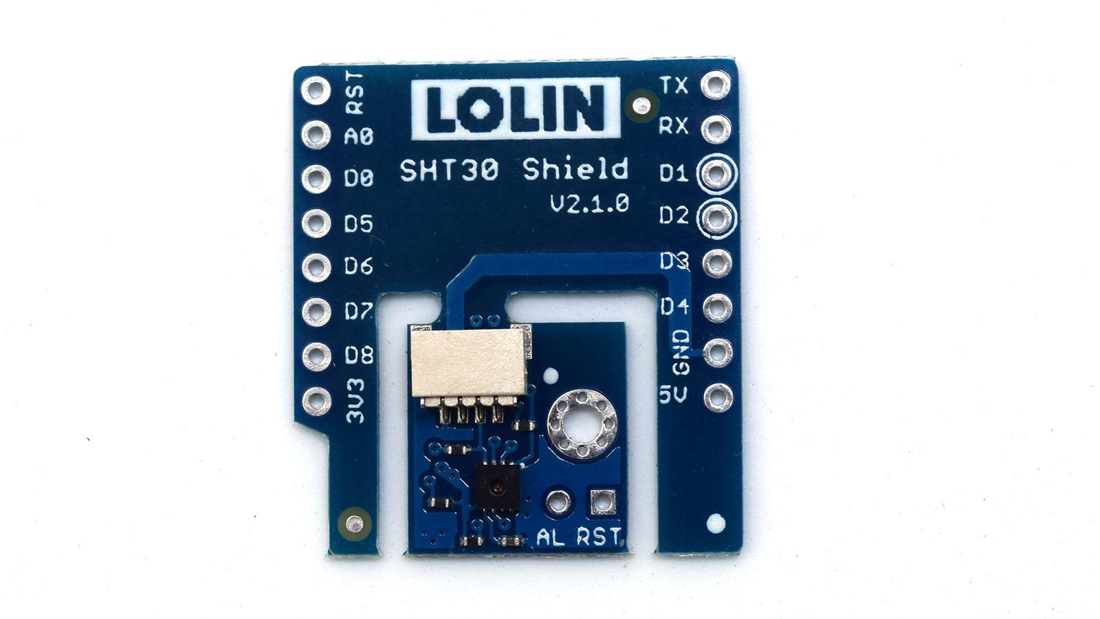
The new digital SHT3x humidity sensor series takes sensor technology to a new level. As the successor of the SHT2x series it is determined to set the next industry standard in humidity sensing.
The SHT3x humidity sensor series consists of a low-cost version with the SHT30 humidity sensor, a standard version with the SHT31 humidity sensor, and a high-end version with the SHT35 humidity sensor.
The SHT3x humidity sensor series combines multiple functions and various interfaces (I2C, analog voltage output) with a applications-friendly, very wide operating voltage range (2.15 to 5.5 V).
More information at sensiron
The sensor is an I2C device so uses D1 and D2
Code
Wemos have their own library so we will use that – https://github.com/wemos/WEMOS_SHT3x_Arduino_Library
I changed the baud rate in Serial.begin, I couldn’t get the example to work. Not sure why . there is also an example which use this and the OLED shield in the github repo, worth looking at
[codesyntax lang=”cpp”]
#include <WEMOS_SHT3X.h>

SHT3X sht30(0x45);

void setup()
{
  Serial.begin(9600);
}

void loop() {

  if(sht30.get()==0){
    Serial.print("Temperature in Celsius : ");
    Serial.println(sht30.cTemp);
    Serial.print("Temperature in Fahrenheit : ");
    Serial.println(sht30.fTemp);
    Serial.print("Relative Humidity : ");
    Serial.println(sht30.humidity);
    Serial.println();
  }
  else
  {
    Serial.println("Error!");
  }
  delay(1000);

}
[/codesyntax]
Open the serial monitor and you should see something like this
Temperature in Celsius : 30.47
Temperature in Fahrenheit : 86.84
Relative Humidity : 40.68
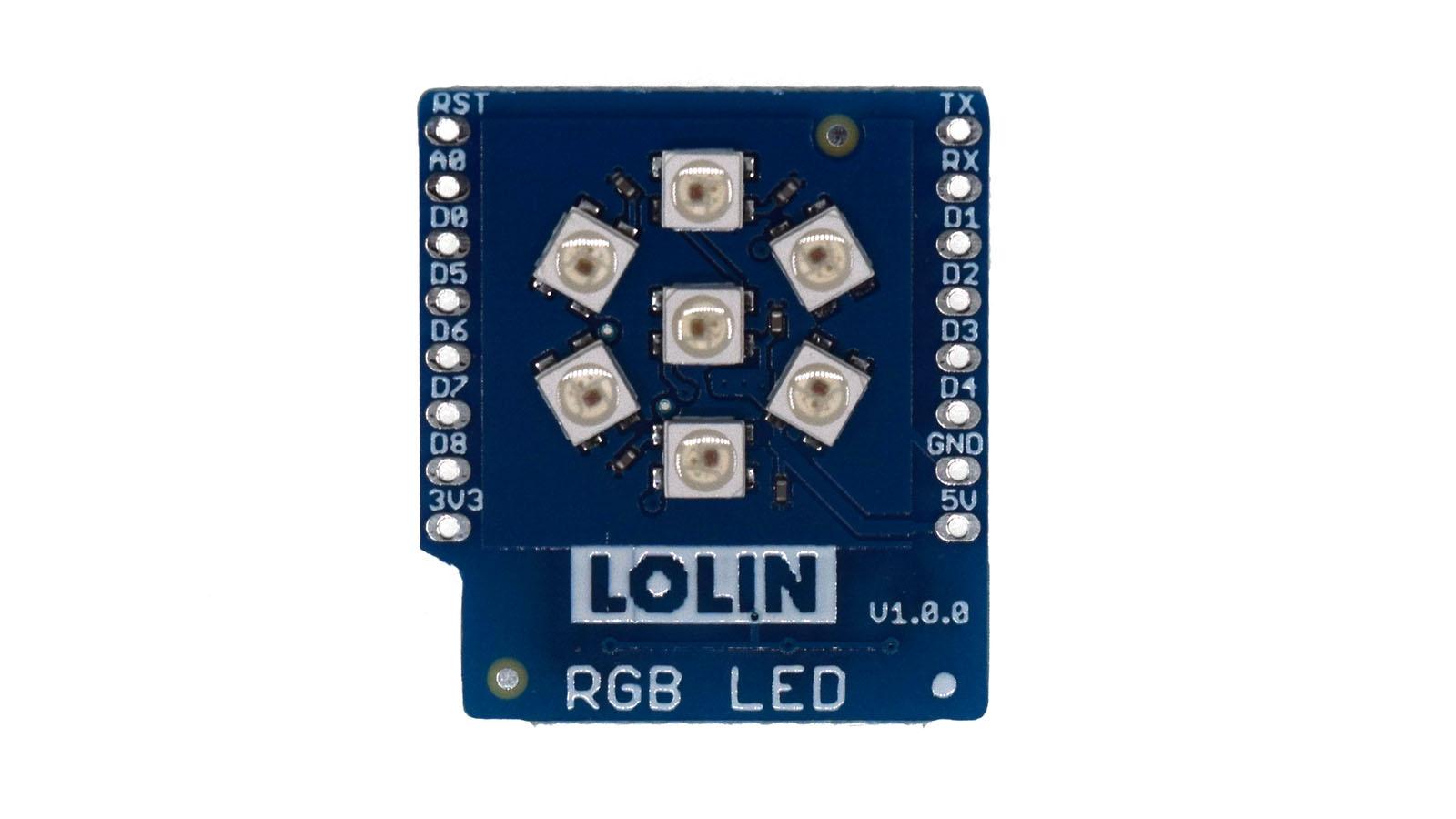
RGB Shield example
In this example we connect a RGB LED shield to a Wemos mini, this is similar to another Wemos shield but this time it has 7 RGB LEDs
The WS2812 is an intelligent control LED light source that the control circuit and RGB chip are integrated in a package of 5050 components. It internal include intelligent digital port data latch and signal reshaping amplification drive circuit.
Also include a precision internal oscillator and a 12V voltage programmable constant current control part, effectively ensuring the pixel point light color height consistent.
The data transfer protocol use single NZR communication mode. After the pixel power-on reset, the DIN port receive data from controller, the first pixel collect initial 24 bit data then sent to the internal data latch, the other data which reshaping by the internal signal reshaping amplification circuit sent to the next cascade pixel through the DO port.
After transmission for each pixel,the signal to reduce 24 bit. pixel adopt auto reshaping transmit technology, making the pixel cascade number is not limited the signal transmission, only depend on the speed of signal transmission.
LED with low driving voltage, environmental protection and energy saving, high brightness, scattering angle is large, good consistency, low power, long life and other advantages. The control chip integrated in LED above becoming more simple circuit, small volume, convenient installation.
Code
You will need to add the Adafruit Neopixel library to your Arduino IDE – https://github.com/adafruit/Adafruit_NeoPixel
[codesyntax lang=”cpp”]
#include <Adafruit_NeoPixel.h>

#define PIN   D4
#define LED_NUM 7

// When we setup the NeoPixel library, we tell it how many pixels, and which pin to use to send signals.
Adafruit_NeoPixel leds = Adafruit_NeoPixel(LED_NUM, PIN, NEO_GRB + NEO_KHZ800);


void setup()
{
  leds.begin(); // This initializes the NeoPixel library.
}


void led_set(uint8 R, uint8 G, uint8 B)
{
  for (int i = 0; i < LED_NUM; i++)
  {
    leds.setPixelColor(i, leds.Color(R, G, B));
    leds.show();
    delay(150);
  }
}

void loop() {

  led_set(10, 0, 0);//red
  led_set(0, 0, 0);

  led_set(0, 10, 0);//green
  led_set(0, 0, 0);

  led_set(0, 0, 10);//blue
  led_set(0, 0, 0);

}
[/codesyntax]
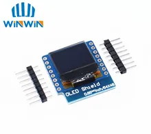
OLED Shield example
In this example we look at another terrific little low cost shield for the Wemos mini, this time its the OLED shield. Lets look at the shield and some specs
- Screen Size: 64×48 pixels (0.66” Across)
- Operating Voltage: 3.3V
- Driver IC: SSD1306
- Interface: IIC(I2C)
- IIC Address: 0x3C or 0x3D
The shield uses the I2C pins, so you can still connect another I2C device (if it uses a different address) and the other pins are available
| D1 mini | Shield |
| D1 | SCL |
| D2 | SDA |
Code
You will need to add the https://github.com/mcauser/Adafruit_SSD1306 library
The following code example is a simple hello world type example
[codesyntax lang=”cpp”]
#include <SPI.h>
#include <Wire.h>
#include <Adafruit_GFX.h>
#include <Adafruit_SSD1306.h>

// SCL GPIO5
// SDA GPIO4
#define OLED_RESET 0  // GPIO0
Adafruit_SSD1306 display(OLED_RESET);

#define NUMFLAKES 10
#define XPOS 0
#define YPOS 1
#define DELTAY 2


#define LOGO16_GLCD_HEIGHT 16
#define LOGO16_GLCD_WIDTH  16


void setup()   {
  Serial.begin(9600);

  display.begin(SSD1306_SWITCHCAPVCC, 0x3C);  // initialize with the I2C addr 0x3C
  // init done

  display.display();
  delay(2000);

  // Clear the buffer.
  display.clearDisplay();

  // text display tests
  display.setTextSize(1);
  display.setTextColor(WHITE);
  display.setCursor(0,0);
  display.println("Hello, world!");
  display.display();
  delay(2000);
  display.clearDisplay();

}


void loop() {

}
[/codesyntax]