In this article we look at a shield for an Arduino which is an ideal resource for learning. The shield is commonly known as the Easy module shield and contains the following components.
It has two pushbutton switches
There are two LEDs
One RGB LED
Infrared receiving module
Light dependent resistor
Buzzer
Potentiometer
DHT11 temperature and humidity sensor module
You also get an LM35 temperature sensor
The following come out to external connectors so you can connect other modules or components
One I2C interface (A4 SDA, A5 SCL)
One TTL serial port
Two way digital port (D7 and、D8)
analog port (A3)
The shield looks like this
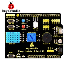
As you can see there are many components on the shield and this means you can create a lot of examples and therefore this is ideal learning resource and with the lack of breadboards , individual components and connecting wire it is arguably easier to use. In this article we will be showing you some examples of some of the features of the Easy Module Shield
Parts List
| Name | Link |
| Arduino Uno | UNO R3 CH340G/ATmega328P, compatible for Arduino UNO |
| Multi-purpose Shield V1 | keyestudio Multi-purpose Shield V1 for arduino starter |
Code Examples
We do not cover all of the functionality of the shield but we have several examples below
LED Example
Overview
There are 2 LEDs connected to D12 and D13 on the Easy Module Shield
Code
[codesyntax lang=”cpp”]
#define redLed 12
#define blueLed 13
void setup()
{
// initialize serial communication at 9600 bits per second:
pinMode(redLed, OUTPUT);
pinMode(blueLed, OUTPUT);
}
void loop()
{
digitalWrite(redLed, HIGH); // turn the LED on (HIGH is the voltage level)
digitalWrite(blueLed, LOW); // turn the LED off by making the voltage LOW
delay(1000);
digitalWrite(redLed, LOW); // turn the LED off by making the voltage LOW
digitalWrite(blueLed, HIGH); // turn the LED on (HIGH is the voltage level)
delay(1000);
}
[/codesyntax]
Upload to your Arduino and you should see the LEDs flash
RGB LEDs
Overview
The Easy Module Shield has a common cathode RGB LED fitted to it, this uses pins D9, D10 and D11. As this is a common cathode type then a 1 (HIGH) will switch an LED on and a 0 (LOW) switches the LED off.
As the board uses D9, 10 and 11 these are all PWM pins, this means you can also use AnalogWrite and send a value from 0 to 255 to each pin, this alters the duty cycle which in turn means that you can generate the effect of varying the brightness of the LED
Code
This first example just uses DigitalWrite to set an LED pin high or low
[codesyntax lang=”cpp”]
#define redLed 9
#define greenLed 10
#define blueLed 11
void setup()
{
// initialize serial communication at 9600 bits per second:
pinMode(redLed, OUTPUT);
pinMode(blueLed, OUTPUT);
pinMode(greenLed, OUTPUT);
}
void loop()
{
digitalWrite(redLed, HIGH); // turn the LED on (HIGH is the voltage level)
delay(1000);
digitalWrite(redLed, LOW); // turn the LED off by making the voltage LOW
delay(1000);
digitalWrite(blueLed, HIGH); // turn the LED on (HIGH is the voltage level)
delay(1000);
digitalWrite(blueLed, LOW); // turn the LED off by making the voltage LOW
delay(1000);
digitalWrite(greenLed, HIGH); // turn the LED on (HIGH is the voltage level)
delay(1000);
digitalWrite(greenLed, LOW); // turn the LED off by making the voltage LOW
delay(1000);
}
[/codesyntax]
You can also use the AnalogWrite function and set the pins to a value of 0 to 255, this example shows how to set the various colors using this method
[codesyntax lang=”cpp”]
#define redLed 9
#define greenLed 10
#define blueLed 11
void setup()
{
pinMode(redLed, OUTPUT);
pinMode(greenLed, OUTPUT);
pinMode(blueLed, OUTPUT);
}
void loop()
{
setColor(255, 0, 0); // red
delay(1000);
setColor(0, 255, 0); // green
delay(1000);
setColor(0, 0, 255); // blue
delay(1000);
setColor(255, 255, 0); // yellow
delay(1000);
setColor(80, 0, 80); // purple
delay(1000);
setColor(0, 255, 255); // aqua
delay(1000);
setColor(255, 255, 255); // white
delay(1000);
setColor(0, 0, 0); // off
delay(1000);
}
void setColor(int red, int green, int blue)
{
analogWrite(redLed, red);
analogWrite(greenLed, green);
analogWrite(blueLed, blue);
}
Another example which shows us using a for loop to loop from 0 to 255 on the red LED. This produces a kind of pulsing effect on the LED
#define redLed 9
#define greenLed 10
#define blueLed 11
void setup()
{
pinMode(redLed, OUTPUT);
pinMode(greenLed, OUTPUT);
pinMode(blueLed, OUTPUT);
}
void loop()
{
for (int i=0; i <= 255; i++)
{
setColor(i, 0, 0); // red
delay(10);
}
}
void setColor(int red, int green, int blue)
{
analogWrite(redLed, red);
analogWrite(greenLed, green);
analogWrite(blueLed, blue);
}
[/codesyntax]
LDR example
Overview
A photoresistor (or light-dependent resistor, LDR, or photo-conductive cell) is a light-controlled variable resistor. The resistance of a photoresistor decreases with increasing incident light intensity; in other words, it exhibits photoconductivity. A photoresistor can be applied in light-sensitive detector circuits, and light-activated and dark-activated switching circuits.
The Easy Module Shield has an LDR connected to A1
Code
[codesyntax lang=”cpp”]
#define ldrPin A1
void setup()
{
// initialize serial communication at 9600 bits per second:
Serial.begin(9600);
}
void loop()
{
// read the LDR on analog pin 1:
float ldrValue = analogRead(ldrPin);
// Convert the analog reading to a voltage
float ldrVoltage = ldrValue * (5.0 / 1023.0);
// print out the LDR value you read:
Serial.print(“LDR value : “);
Serial.println(ldrVoltage);
delay(1000);
}
[/codesyntax]
Output
LDR value : 4.09
LDR value : 1.26
LDR value : 3.72
LDR value : 1.61
Pot example
Overview
The Easy Module Shield has a POT connected to A0, you can adjust the pot and read in the analog value , we will display in the serial monitor in our example
Code
[codesyntax lang=”cpp”]
#define vrPin A0
void setup()
{
// initialize serial communication at 9600 bits per second:
Serial.begin(9600);
}
void loop()
{
// read the variable resistor on analog pin 0:
float vrValue = analogRead(vrPin);
// Convert the analog reading to a voltage
float vrVoltage = vrValue * (5.0 / 1023.0);
// print out the Variable resistor value you read:
Serial.print(“Variable resistor : “);
Serial.println(vrVoltage);
delay(1000);
}
[/codesyntax]
Output
Variable resistor : 2.36
Variable resistor : 3.37
Variable resistor : 4.53
Variable resistor : 0.00
LM35 example
Overview
The LM35 series are precision integrated-circuit temperature devices with an output voltage linearly-proportional to the Centigrade temperature. The LM35 device does not require any external calibration or trimming to provide typical accuracies of ±¼°C at room temperature and ±¾°C over a full −55°C to 150°C temperature range. The device is used with single power supplies, or with plus and minus supplies. As the LM35 device draws only 60 µA from the supply, it has very low self-heating of less than 0.1°C in still air
Code
[codesyntax lang=”cpp”]
//declare variables
float tempC;
int tempPin = 2;
void setup()
{
Serial.begin(9600); //opens serial port
}
void loop()
{
tempC = analogRead(tempPin); //read the value from the sensor
tempC = (5.0 * tempC * 100.0)/1024.0; //convert the analog data to temperature
Serial.print((byte)tempC);
Serial.println(” C”);
delay(1000);
}
[/codesyntax]
Output
23 C
24 C
25 C
26 C
Button Example
Overview
The Easy Module Shield has 2 buttons fitted to it and these are connected to D2 and D3
Code
example 1
[codesyntax lang=”cpp”]
const int buttonPin = 3; // the number of the pushbutton pin
const int ledPin = 12; // the number of the LED pin
int buttonState = 0; // variable for reading the pushbutton status
void setup()
{
// initialize the LED pin as an output:
pinMode(ledPin, OUTPUT);
pinMode(buttonPin, INPUT);
}
void loop()
{
// read the state of the pushbutton value:
buttonState = digitalRead(buttonPin);
// check if the pushbutton is pressed.
// if it is, the buttonState is LOW:
if (buttonState == LOW)
{
// turn LED on:
digitalWrite(ledPin, HIGH);
}
else
{
// turn LED off:
digitalWrite(ledPin, LOW);
}
}
[/codesyntax]
There you go we haven’t covered the buzzer, DHT11 or IR receiver. See if you can create examples for these components. The buzzer could use the tone library, there are several DHT11 libraries with good code examples and there are also IR reciever libraries
Some ideas
DHT11 and LM35 comparison
Temperature based alarm (buzzer or LED)
Light or darkness alarm (buzzer or LED)
Ir keys switch on and off various LEDs