In this article we will look at the Multi function shield, just so you know the shield we are talking about here this is a picture of it.
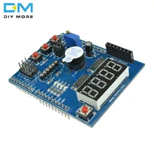
We will look at the features of this board and show you some examples to use these
Features
It has a 4 digit 7-segment LED display module which is driven by two serial 74HC595’s
4 LED’s
10K potentiometer
3 x push buttons
Piezo buzzer
DS18B20 or LM35 temperature sensor interface (the sensor is not included)
TSOP1838 Infrared receiver interface (IR receiver is not included)
Serial interface header for connection to serial modules
APC220 wireless module interface (serial/UART interface)
There are 4 available I/Os on a header – these are 5, 6 and 9 and A5
As you can see some of the features require additional components – you can add an LM35, DS18b20 and a TSOP1838 Infrared receiver if you want to use this functionality, our examples won’t use these parts
I have noticed two drawbacks with the board
1: If you use an Arduino Uno the pins of the LED display on the shield can short out on the USB connector, I had to use insulating tape to cover the pins. Obviously on a Leonardo or one of the Chinese clones which changes the USB port that is not an issue
2: U5 is used for the DS18b20 and the LM35 and the board has the outline of the part on the mask but for the LM35 has to be inserted the opposite way round to the mask. I actually saw a guide which recommended swapping it round if it got – amazing
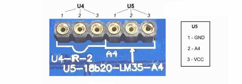
My only other complaint was using A4 for the DS18b20/LM35 data pin – if this has been left it could have been brought to a header and used as an I2C connector on an Arduino Uno and they could have used one of the other available pins making this shield even more useful.
Parts List
You can pick up one of these shields for around the $2 from the link below, along with a $3 Arduino uno that makes a nice beginners kit
| Name | Link |
| Arduino Uno | UNO R3 CH340G/ATmega328P, compatible for Arduino UNO |
| Multi Function shield | Multi Function Shield for Arduino |
Code Examples
Blinking LED
[codesyntax lang=”cpp”]
int led = 13;

void setup()
{
// initialize the digital pin as an output.
pinMode(led, OUTPUT);
}

void loop()
{
digitalWrite(led, HIGH);
delay(1000);
digitalWrite(led, LOW);
delay(1000);
}
[/codesyntax]
All LEDS blinking
[codesyntax lang=”cpp”]
int led1 = 13;
int led2 = 12;
int led3 = 11;
int led4 = 10;

void setup()
{
// initialize the digital pin as an output.
pinMode(led1, OUTPUT);
pinMode(led2, OUTPUT);
pinMode(led3, OUTPUT);
pinMode(led4, OUTPUT);
}

void loop()
{
digitalWrite(led1, HIGH);
digitalWrite(led2, HIGH);
digitalWrite(led3, HIGH);
digitalWrite(led4, HIGH);
delay(1000);
digitalWrite(led1, LOW);
digitalWrite(led2, LOW);
digitalWrite(led3, LOW);
digitalWrite(led4, LOW);
delay(1000);
}
[/codesyntax]
Switches example
[codesyntax lang=”cpp”]
const byte LED[] = {13,12,11,10};

#define BUTTON1 A1
#define BUTTON2 A2

void setup()
{
// initialize the digital pin as an output.
/* Set each pin to outputs */
pinMode(LED[0], OUTPUT);
pinMode(LED[1], OUTPUT);
pinMode(LED[2], OUTPUT);
pinMode(LED[3], OUTPUT);
}

void loop()
{
if(!digitalRead(BUTTON1))
{
digitalWrite(LED[0], HIGH);
digitalWrite(LED[1], HIGH);
digitalWrite(LED[2], HIGH);
digitalWrite(LED[3], HIGH);
}

if(!digitalRead(BUTTON2))
{
digitalWrite(LED[0], LOW);
digitalWrite(LED[1], LOW);
digitalWrite(LED[2], LOW);
digitalWrite(LED[3], LOW);
}
}
[/codesyntax]
Potentiometer 1
[codesyntax lang=”cpp”]
#define Pot1 0

void setup()
{
Serial.begin(9600);
}

/* Main Program */
void loop()
{

Serial.print(“Potentiometer reading: “);
Serial.println(analogRead(Pot1));
/* Wait 0.5 seconds before reading again */
delay(500);
}
[/codesyntax]
Pot and led
[codesyntax lang=”cpp”]
const byte LED[] = {13,12,11,10};
#define Pot1 0

void setup()
{
Serial.begin(9600);
// initialize the digital pin as an output.
/* Set each pin to outputs */
pinMode(LED[0], OUTPUT);
pinMode(LED[1], OUTPUT);
pinMode(LED[2], OUTPUT);
pinMode(LED[3], OUTPUT);
}

/* Main Program */
void loop()
{
int PotValue;
//Serial.print(“Potentiometer reading: “);
PotValue = analogRead(Pot1);
/* Wait 0.5 seconds before reading again */
if(PotValue < 400)
{
digitalWrite(LED[0], LOW);
digitalWrite(LED[1], LOW);
digitalWrite(LED[2], LOW);
digitalWrite(LED[3], LOW);
Serial.print(“Potentiometer: “);
Serial.println(PotValue);
}
else
{
digitalWrite(LED[0], HIGH);
digitalWrite(LED[1], HIGH);
digitalWrite(LED[2], HIGH);
digitalWrite(LED[3], HIGH);
Serial.print(“Potentiometer: “);
Serial.println(PotValue);
}
delay(500);
}
[/codesyntax]
segment display
[codesyntax lang=”cpp”]
/* Define shift register pins used for seven segment display */
#define LATCH_DIO 4
#define CLK_DIO 7
#define DATA_DIO 8

/* Segment byte maps for numbers 0 to 9 */
const byte SEGMENT_MAP[] = {0xC0,0xF9,0xA4,0xB0,0x99,0x92,0x82,0xF8,0X80,0X90};
/* Byte maps to select digit 1 to 4 */
const byte SEGMENT_SELECT[] = {0xF1,0xF2,0xF4,0xF8};

void setup ()
{
/* Set DIO pins to outputs */
pinMode(LATCH_DIO,OUTPUT);
pinMode(CLK_DIO,OUTPUT);
pinMode(DATA_DIO,OUTPUT);
}

/* Main program */
void loop()
{

/* Update the display with the current counter value */
WriteNumberToSegment(0 , 0);
WriteNumberToSegment(1 , 1);
WriteNumberToSegment(2 , 2);
WriteNumberToSegment(3 , 3);
}

/* Write a decimal number between 0 and 9 to one of the 4 digits of the display */
void WriteNumberToSegment(byte Segment, byte Value)
{
digitalWrite(LATCH_DIO,LOW);
shiftOut(DATA_DIO, CLK_DIO, MSBFIRST, SEGMENT_MAP[Value]);
shiftOut(DATA_DIO, CLK_DIO, MSBFIRST, SEGMENT_SELECT[Segment] );
digitalWrite(LATCH_DIO,HIGH);
}
[/codesyntax]
Read pot and display value on display
[codesyntax lang=”cpp”]
/* Define shift register pins used for seven segment display */
#define LATCH_DIO 4
#define CLK_DIO 7
#define DATA_DIO 8

#define Pot1 0

/* Segment byte maps for numbers 0 to 9 */
const byte SEGMENT_MAP[] = {0xC0,0xF9,0xA4,0xB0,0x99,0x92,0x82,0xF8,0X80,0X90};
/* Byte maps to select digit 1 to 4 */
const byte SEGMENT_SELECT[] = {0xF1,0xF2,0xF4,0xF8};

void setup ()
{
Serial.begin(9600);
/* Set DIO pins to outputs */
pinMode(LATCH_DIO,OUTPUT);
pinMode(CLK_DIO,OUTPUT);
pinMode(DATA_DIO,OUTPUT);
}

/* Main program */
void loop()
{
int PotValue;
PotValue = analogRead(Pot1);
Serial.print(“Potentiometer: “);
Serial.println(PotValue);
/* Update the display with the current counter value */
WriteNumberToSegment(0 , PotValue / 1000);
WriteNumberToSegment(1 , (PotValue / 100) % 10);
WriteNumberToSegment(2 , (PotValue / 10) % 10);
WriteNumberToSegment(3 , PotValue % 10);
}

/* Write a decimal number between 0 and 9 to one of the 4 digits of the display */
void WriteNumberToSegment(byte Segment, byte Value)
{
digitalWrite(LATCH_DIO,LOW);
shiftOut(DATA_DIO, CLK_DIO, MSBFIRST, SEGMENT_MAP[Value]);
shiftOut(DATA_DIO, CLK_DIO, MSBFIRST, SEGMENT_SELECT[Segment] );
digitalWrite(LATCH_DIO,HIGH);
}
[/codesyntax]
Downloads
I found these downloads, a schematic and code examples with chinese comments, not that difficult to understand what the examples do