In this article we look at the MAG3110 magnetometer, we will discuss the sensor and also show how to connect the sensor to a Raspberry Pi and an Arduino with code examples for both
Freescale’s MAG3110 is a small, low-power, digital 3-axis magnetometer. The device can be used in conjunction with a 3-axis accelerometer to realize an orientation independent electronic compass that can provide accurate heading information. It features a standard I2C serial interface output and smart embedded functions.
The MAG3110 is capable of measuring magnetic fields with an output data rate (ODR) up to 80 Hz; these output data rates correspond to sample intervals from 12.5 ms to several seconds. The MAG3110 is available in a plastic DFN package and it is guaranteed to operate over the extended temperature range of -40°C to +85°C.
Features
80 Hz maximum sampling rate
I²C interface 400 kHz
-40°C to +85°C operation
0.95 to 3.6-volt supply
Full-scale range ±1000 µT
Low-power, single-shot measurement mode
Noise down to 0.25 µT rms
Sensitivity of 0.10 µµT
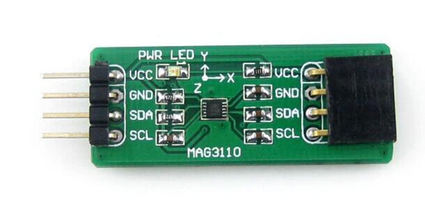
Again for ease to use its easier to buy a module with the device fitted to it, here is one that I purchased. You can see the MAG3110 in the middle of the picture
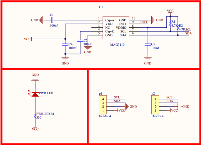
And here is a schematic for a typical MAG3110 module
Parts List
These are the parts that I used for the Raspberry Pi example
For the Arduino example we used the following parts
| Name | Link |
| Arduino Uno | UNO R3 CH340G/ATmega328P, compatible for Arduino UNO |
| MAG3110 module | MAG3110 module electronic compass module |
| Connecting wire | Free shipping Dupont line 120pcs 20cm male to male + male to female and female to female jumper wire |
Schematics and Connection
The MAG3110 module being an I2C module is very easy to connect to many microcontrollers, we will show you an Arduino example and a Raspberry Pi example
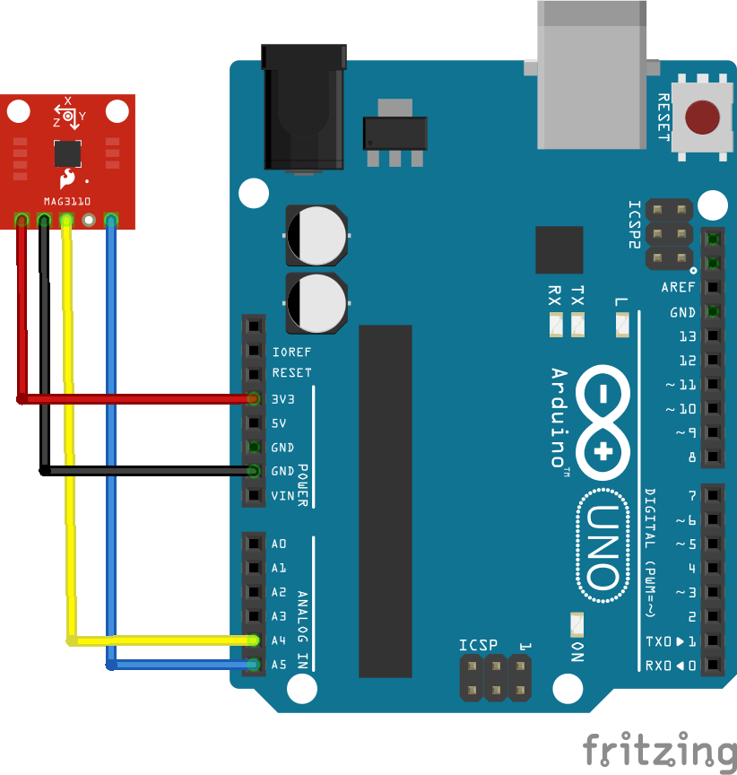
Arduino connection
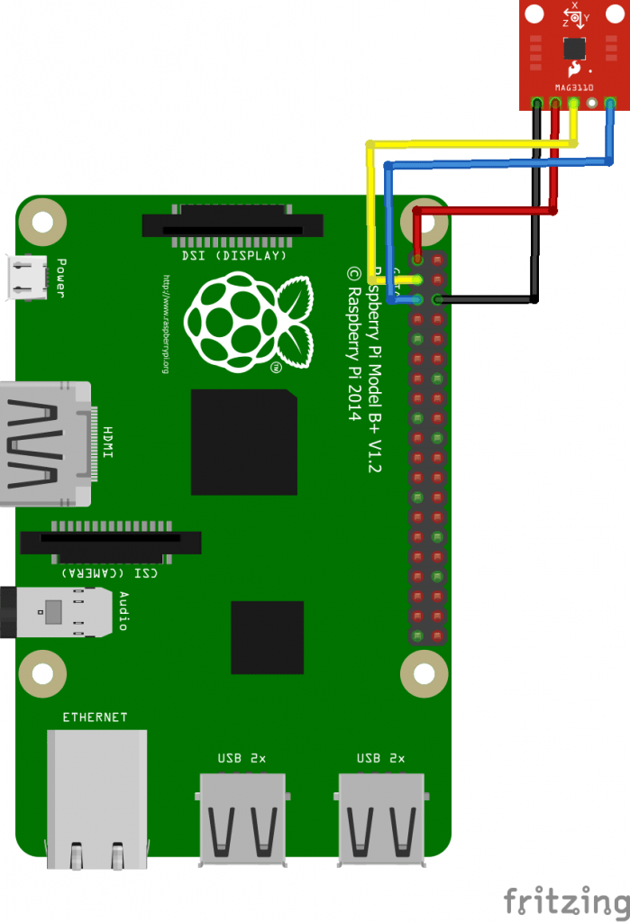
Raspberry Pi connection
Arduino Code Example
This code example does not require any libraries
[codesyntax lang=”cpp”]
#include <Wire.h>

#define MAG_ADDR  0x0E //7-bit address for the MAG3110, doesn't change

void setup()
{
  Wire.begin();        // join i2c bus (address optional for master)
  Serial.begin(9600);  // start serial for output
  config();            // turn the MAG3110 on
}

void loop()
{
  print_values();
  delay(5);
}

void config(void)
{
  Wire.beginTransmission(MAG_ADDR); // transmit to device 0x0E
  Wire.write(0x11);             // cntrl register2
  Wire.write(0x80);             // write 0x80, enable auto resets
  Wire.endTransmission();       // stop transmitting
  delay(15);
  Wire.beginTransmission(MAG_ADDR); // transmit to device 0x0E
  Wire.write(0x10);             // cntrl register1
  Wire.write(1);                // write 0x01, active mode
  Wire.endTransmission();       // stop transmitting
}

void print_values(void)
{
  Serial.print("x=");
  Serial.print(read_x());
  Serial.print(",");
  Serial.print("y=");
  Serial.print(read_y());
  Serial.print(",");
  Serial.print("z=");
  Serial.println(read_z());
}

int mag_read_register(int reg)
{
  int reg_val;

  Wire.beginTransmission(MAG_ADDR); // transmit to device 0x0E
  Wire.write(reg);              // x MSB reg
  Wire.endTransmission();       // stop transmitting
  delayMicroseconds(2); //needs at least 1.3us free time between start and stop

  Wire.requestFrom(MAG_ADDR, 1); // request 1 byte
  while(Wire.available())    // slave may write less than requested
  {
    reg_val = Wire.read(); // read the byte
  }

  return reg_val;
}

int mag_read_value(int msb_reg, int lsb_reg)
{
  int val_low, val_high;  //define the MSB and LSB
  val_high = mag_read_register(msb_reg);
  delayMicroseconds(2); //needs at least 1.3us free time between start and stop
  val_low = mag_read_register(lsb_reg);
  int out = (val_low|(val_high << 8)); //concatenate the MSB and LSB
  return out;
}

int read_x(void)
{
  return mag_read_value(0x01, 0x02);
}

int read_y(void)
{
  return mag_read_value(0x03, 0x04);
}

int read_z(void)
{
  return mag_read_value(0x05, 0x06);
}
[/codesyntax]
Testing
Open up the serial monitor
x=44,y=1138,z=1505
x=65175,y=580,z=2037
x=65117,y=745,z=1435
x=65145,y=1487,z=1814
x=64700,y=949,z=1912
x=64848,y=671,z=1921
x=65411,y=803,z=2218
x=64852,y=720,z=1644
Raspberry Pi Code example
Save the following code as mag3110.py
[codesyntax lang=”python”]
import smbus
import time

bus = smbus.SMBus(1)

# MAG3110 I2C address 0x0E
# Select Control register, 0x10(16)
bus.write_byte_data(0x0E, 0x10, 0x01)

time.sleep(0.5)

# MAG3110 I2C address 0x0E
# Read data back from 0x01(1), 6 bytes
data = bus.read_i2c_block_data(0x0E, 0x01, 6)

# Convert the data
xMag = data[0] * 256 + data[1]
if xMag > 32767 :
	xMag -= 65536

yMag = data[2] * 256 + data[3]
if yMag > 32767 :
	yMag -= 65536

zMag = data[4] * 256 + data[5]
if zMag > 32767 :
	zMag -= 65536

# Output data
print "X-Axis : %d" %xMag
print "Y-Axis : %d" %yMag
print "Z-Axis : %d" %zMag
[/codesyntax]
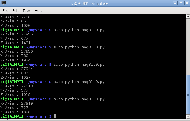
Run the code above – sudo python mag3110.py
Testing
Tested with
ESP32, ESP8266, Arduino, Linkit and Micro:bit all using the Arduino IDE
Raspberry Pi
Links
https://www.nxp.com/docs/en/data-sheet/MAG3110.pdf