The MCP4725 is a single channel, 12-bit, voltage output Digital-to-Analog Converter with integrated EEPROM and an I2C Compatible Serial Interface.
Features
12-Bit Resolution
On-Board Non-Volatile Memory (EEPROM)
±0.2 LSB DNL (typ)
External A0 Address Pin
Normal or Power-Down Mode
Fast Settling Time of 6µs (typ)
External Voltage Reference (VDD)
Rail-to-Rail Output
Low Power Consumption
Single-Supply Operation: 2.7V to 5.5V
I2CTM Interface:
Eight Available Addresses
Standard (100 kbps), Fast (400 kbps) andHigh Speed (3.4 Mbps) Modes
Small 6-lead SOT-23 Package
Extended Temperature Range: -40°C to +125°C
As this is a 12 bit DAC converter. What this means is that it will accept up to 4096 possible inputs to provide an analog output, where an output value of zero is zero and an output value of 4095 is full scale.
Full scale is determined by the reference voltage you supply to the VCC pin. Also you can see from above that the supply voltage can be anywhere from 2.7 volts to 5.5 volts. We will use 5v, or as close as what is supplied via the USB in. You may want to measure this voltage for accurate readings, I’ve seen this vary.
This means that to work out the value of the Least Significant Bit (LSB) is as follows:
1 LSB = VCC Voltage / 4096
Again the easiest way to interface this to an Arduino is to purchase a module, tehse are available from many sources, here is what my one looked at.
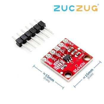
Parts Required
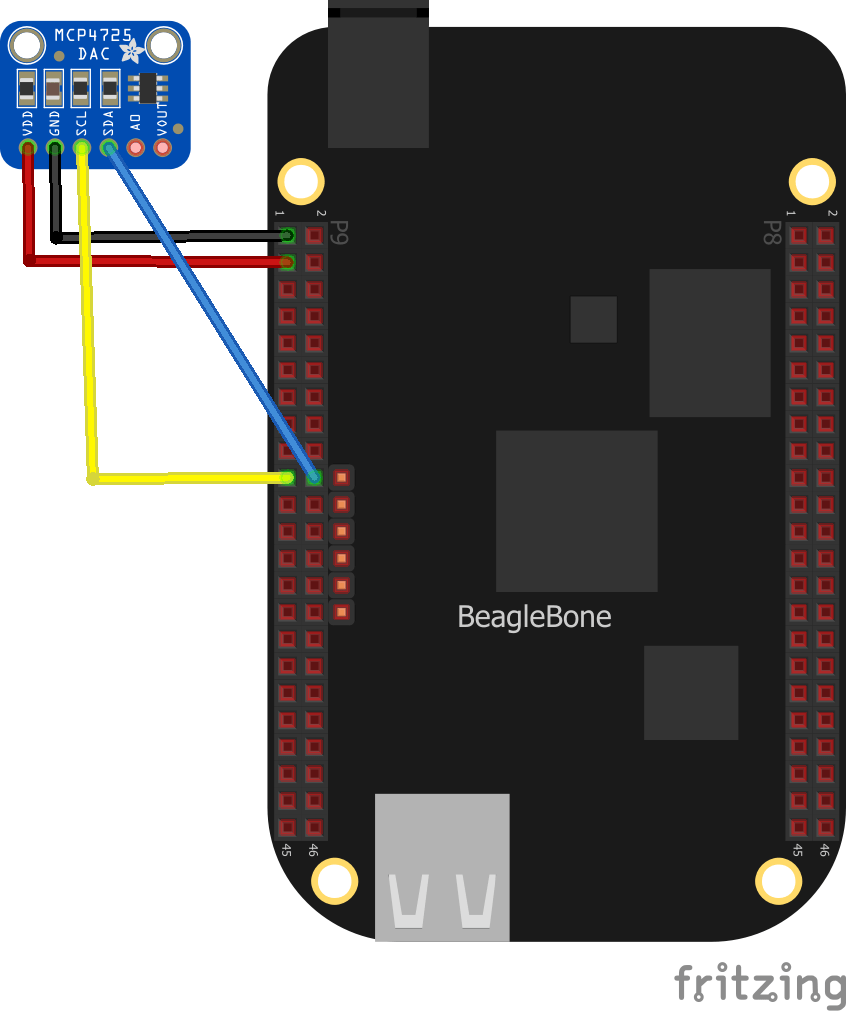
Connection
| Beaglebone | Module |
| 3.3v – P9.3 | Vcc |
| Gnd – P9.1 | Gnd |
| SDA – P9.20 | SDA |
| SCL – P9.19 | SCL |
Code
Install the Adafruit library from the terminal on your Beaglebone – I use the Cloud 9 IDE
sudo pip install adafruit-mcp4725This is the example
[codesyntax lang=”python”]
# Simple demo of setting the output voltage of the MCP4725 DAC.
# Will alternate setting 0V, 1/2VDD, and VDD each second.
# Author: Tony DiCola
# License: Public Domain
import time

# Import the MCP4725 module.
import Adafruit_MCP4725

# Create a DAC instance.
dac = Adafruit_MCP4725.MCP4725(address=0x60, busnum=2)

# Note you can change the I2C address from its default (0x62), and/or the I2C
# bus by passing in these optional parameters:
#dac = Adafruit_MCP4725.MCP4725(address=0x49, busnum=1)

# Loop forever alternating through different voltage outputs.
print('Press Ctrl-C to quit...')
while True:
    print('Setting voltage to 0!')
    dac.set_voltage(0)
    time.sleep(2.0)
    print('Setting voltage to 1/2 Vdd!')
    dac.set_voltage(2048)  # 2048 = half of 4096
    time.sleep(2.0)
    print('Setting voltage to Vdd!')
    dac.set_voltage(4096, True)
    time.sleep(2.0)
[/codesyntax]
Output
You can see the results below
debian@beaglebone:/var/lib/cloud9/MCP4725$ python test_MCP4725.py
Press Ctrl-C to quit…
Setting voltage to 0!
Setting voltage to 1/2 Vdd!
Setting voltage to Vdd!
Setting voltage to 0!
Setting voltage to 1/2 Vdd!
Setting voltage to Vdd!
Setting voltage to 0!
Setting voltage to 1/2 Vdd!