In this article we look at an RGB LED connected to a Beaglebone.
An RGB LED is a combination of 3 LEDs in one package:
1x Red LED
1x Green LED
1x Blue LED
By switching on and off these LEDs we can make up different basic colors and by configuring the intensity of each LED, you can produce other colors as well. To do this we commonly use PWM.
In fact there are two different types of RGB LEDs, there is a common anode type which means all three LEDs share a positive connection and a common cathode type which means all three LEDs share a negative connection. In this example we use a common anode. What this means that when one of the RGB pins is a logic low that color will switch on and when the pins are logic high the color will switch off. If you have a common cathode type it is the opposite.
Parts Required
| Name | Link |
| Beaglebone | BeagleBone Black TI AM3358 Cortex-A8 development BB-Black Rev.C |
| RGB LED | 3 Color RGB LED Sensor Module |
| Connecting wire | Dupont line 120pcs 20cm male to male + male to female and female to female jumper wire |
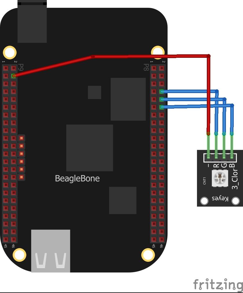
Schematic/Connection
I used a module which had built in resistors, as stated it was a common anode type
Code Examples
We use the adafruit GPIO library
Example 1
This example simply switches all the LEDs on and off – so your RGB LED will look like it s white, or fairly close to that
[codesyntax lang=”python”]
import Adafruit_BBIO.GPIO as GPIO
import time

GPIO.setup("P8_8", GPIO.OUT)
GPIO.setup("P8_10", GPIO.OUT)
GPIO.setup("P8_12", GPIO.OUT)


while True:
    GPIO.output("P8_8", GPIO.HIGH)
    GPIO.output("P8_10", GPIO.HIGH)
    GPIO.output("P8_12", GPIO.HIGH)
    time.sleep(1)
    GPIO.output("P8_8", GPIO.LOW)
    GPIO.output("P8_10", GPIO.LOW)
    GPIO.output("P8_12", GPIO.LOW)
    time.sleep(1)
[/codesyntax]
Example 2
This example just switches the red part of the RGB led on and off
[codesyntax lang=”python”]
import Adafruit_BBIO.GPIO as GPIO
import time

GPIO.setup("P8_8", GPIO.OUT)
GPIO.setup("P8_10", GPIO.OUT)
GPIO.setup("P8_12", GPIO.OUT)


while True:
    GPIO.output("P8_8", GPIO.HIGH)
    GPIO.output("P8_10", GPIO.HIGH)
    GPIO.output("P8_12", GPIO.HIGH)
    time.sleep(1)
    GPIO.output("P8_8", GPIO.LOW)
    GPIO.output("P8_10", GPIO.HIGH)
    GPIO.output("P8_12", GPIO.HIGH)
    time.sleep(1)
[/codesyntax]
Example 3
This example circles through the red, green and blue colors
[codesyntax lang=”python”]
import Adafruit_BBIO.GPIO as GPIO
import time

GPIO.setup("P8_8", GPIO.OUT)
GPIO.setup("P8_10", GPIO.OUT)
GPIO.setup("P8_12", GPIO.OUT)


while True:
    GPIO.output("P8_8", GPIO.LOW)
    GPIO.output("P8_10", GPIO.HIGH)
    GPIO.output("P8_12", GPIO.HIGH)
    time.sleep(1)
    GPIO.output("P8_8", GPIO.HIGH)
    GPIO.output("P8_10", GPIO.LOW)
    GPIO.output("P8_12", GPIO.HIGH)
    time.sleep(1)
    GPIO.output("P8_8", GPIO.HIGH)
    GPIO.output("P8_10", GPIO.HIGH)
    GPIO.output("P8_12", GPIO.LOW)
    time.sleep(1)
[/codesyntax]