The Arduino MKR1000 is an ideal board for IoT related projects it combines the functionality of the Arduino Zero and the Wi-Fi Shield in one small module. First we will look at the specs and features of the board.
Arduino MKR1000 has been designed to offer a practical and cost effective solution for makers seeking to add WiFi connectivity to their projects with minimal previous experience in networking. The design includes a Li-Po charging circuit that allows the Arduino MKR1000 to run on battery power or external 5V, charging the Li-Po battery while running on external power. Switching from one source to the other is done automatically.
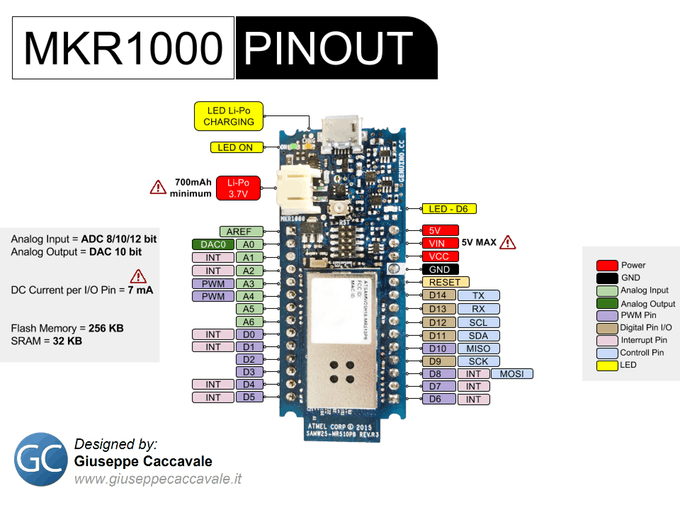
Arduino MKR1000 Pin Description
Unlike most Arduino boards, the MKR1000 runs at 3.3V. The maximum voltage that the I/O pins can tolerate is 3.3V. Applying voltages higher than 3.3V to any I/O pin could damage the board. While output to 5V digital devices is possible, bidirectional communication with 5V devices needs proper level shifting.
| Pin Category | Pin Name | Details |
| Power | Li-Po(3.7v),Vin, Vcc, 5V, GND | Lip-Po(3.7V): The board can be powered by connecting a lithium polymer battery to this pin. The battery should have a nominal voltage of 3.7V and minimum of 700mAh
Vin: The board can be powered by a regulated 5V supply connected to this input pin. The maximum voltage for this pin is 6V 5V: If powered though USB then this output pin can be used to get a +5V supply for powering other circuit Vcc: This pin outputs a regulated 3.3V by using the on board regulator. GND: Ground pins. |
| Reset | Reset | Resets the microcontroller. |
| Analog Pins | A0 – A6 | These 7 pins are used to measure analog voltage in the range of 0-3.3V, with a resolution of 8/10/12 bit |
| DAC Pin | DAC0 | Provides an analog voltage based in the digital input with a resolution of 10 bit |
| Input/Output Pins | Digital Pins D0 – D14 | Can be used as input or output pins. 0V and 3.3V |
| Serial | Rx, Tx | Used to receive and transmit serial data. |
| External Interrupts | 0, 1, 4, 5, 6, 7, 8, A1 -or 16-, A2 – or 17 | These 8 pins can be used as an external interrupt |
| PWM | 0, 1, 2, 3, 4, 5, 6, 7, 8, 10, A3 – or 18 -, A4 -or 19 | The 12 pins can be used to provide 8-bit PWM. |
| SPI | 10(MOSI), 12 (MISO) and 9 (SCK) | Used for SPI communication. |
| Inbuilt LED | 6 | There is a built in LED connected to pin 6. |
| IIC | 11 (SDA), 12 (SCL) | These are used for I2C/TWI communication. |
| AREF | AREF | This provides a reference voltage for input voltage. |
Arduino MKR1000 Pinout
Arduino MKR1000 Technical Specifications
| Microcontroller | SAMD21 Cortex-M0+ 32bit low power ARM MCU |
| Operating Voltage | 3.3V |
| Recommended Input Voltage for Vin pin | Regulated 5V |
| Analog Input Pins | 7 (A0 – A6) |
| Digital I/O Pins | 8 |
| DC Current on I/O Pins | 7 mA |
| DC Current on 3.3V Pin | 50 mA |
| Flash Memory | 256 KB |
| SRAM | 32 KB |
| EEPROM | no |
| Frequency (Clock Speed) | 32.768 kHz (RTC), 48 MHz |
| Communication | IIC, SPI, USART |
Use your Arduino MKR1000 with the Arduino IDE
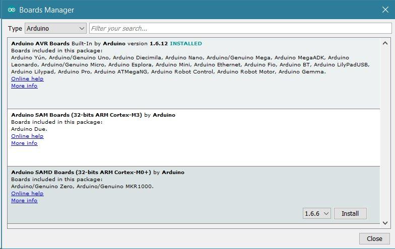
If you want to program your MKR1000 while offline you need to install the Arduino Desktop IDE and add the Atmel SAMD Core to it. This procedure is done by selecting the Tools menu, then Boards and last Boards Manager.
Arduino MKR1000 Connection
Connect the Arduino MKR1000 to your computer using a micro USB cable and wait for it to connect successfully. In the Arduino IDE, select the “Arduino/Genuino MKR1000” board and the correct COM port.
Code
The blink sketch is the easiest way of testing, you will need to change the LED to pin 6 instead of 13
[codesyntax lang=”cpp”]
int led = 6;

// the setup routine runs once when you press reset:
void setup() {
  // initialize the digital pin as an output.
  pinMode(led, OUTPUT);
}

// the loop routine runs over and over again forever:
void loop() {
  digitalWrite(led, HIGH);   // turn the LED on (HIGH is the voltage level)
  delay(1000);               // wait for a second
  digitalWrite(led, LOW);    // turn the LED off by making the voltage LOW
  delay(1000);               // wait for a second
}
[/codesyntax]